
Guide · RS-485 · Modbus
Read industrial sensors 1200 m away with RS-485 & Modbus RTU
I²C and plain UART give up after a metre or two. When you need to reach a sensor across a barn, a boiler room or a factory floor — dozens of nodes, hundreds of metres, electrical noise — the answer is RS-485, and the language spoken on it is usually Modbus RTU. A $1 MAX485 module and an ESP32 get you there.
RS-485 isn’t a new protocol — it’s the same UART frame, just sent over a twisted pair at differential levels, like CAN. That’s where the range and noise immunity come from. If that idea is new, see the RS-232 / RS-485 section of the interactive bus explainer first — it shows why differential beats single-ended on the scope.
Why RS-485 instead of UART
- Differential pair (A/B) — noise hits both wires equally and cancels out. Tens to hundreds of metres instead of centimetres.
- Multi-drop — up to 32 nodes (128 with modern transceivers) on one pair.
- Half-duplex — everyone shares the same pair and takes turns, so you must tell the transceiver when to talk and when to listen.
Wiring a MAX485
The MAX485 is a transceiver: UART on one side, the RS-485 A/B pair on the other. The one non-obvious pin is direction: DE (driver enable) and RE (receiver enable) are tied together and driven by a GPIO — HIGH to transmit, LOW to receive.
MAX485 module            ESP32
-----------              -----
RO  (receiver out)  -->  RX  (e.g. GPIO16)
DI  (driver in)     <--  TX  (e.g. GPIO17)
DE + RE (tied)      <--  DIR (e.g. GPIO4)   // HIGH = transmit, LOW = receive
VCC                 -->  5V (module) / 3V3 logic-safe variants exist
GND                 -->  GND
A / B  -->  twisted pair to the bus (120 Ω at each far end)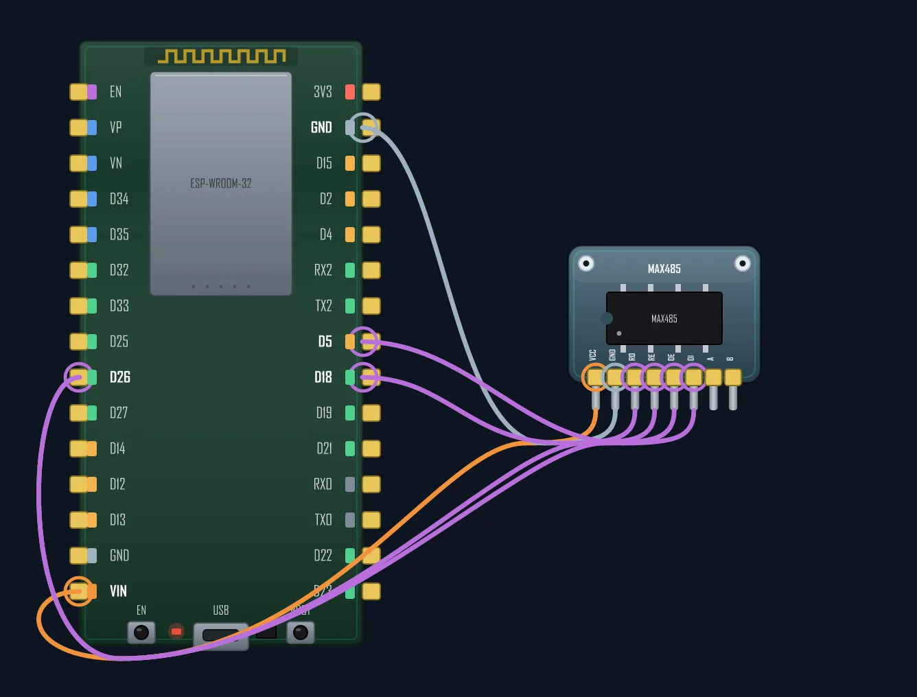
Two hardware rules that bite everyone: put a 120 Ω terminator at each of the two far ends of the bus (not on every node), and keep A→A, B→B down the whole line. On long or quiet buses add bias resistors so the idle line sits at a defined level.
Modbus RTU in one screen
Modbus is a dead-simple master/slave protocol: the master asks, one slave answers, every frame ends
with a CRC. You mostly need two function codes — 0x03 (read holding registers) and
0x04 (read input registers). Here’s an ESP32 reading two registers from slave #1 with the
ModbusMaster library, flipping the direction pin automatically:
#include <ModbusMaster.h>
#define DIR 4                       // DE+RE direction pin
ModbusMaster node;

void preTx()  { digitalWrite(DIR, HIGH); }   // switch driver on before sending
void postTx() { digitalWrite(DIR, LOW);  }   // back to listening after

void setup() {
  pinMode(DIR, OUTPUT); digitalWrite(DIR, LOW);
  Serial2.begin(9600, SERIAL_8N1, 16, 17);   // RS-485 UART
  node.begin(1, Serial2);                     // slave address 1
  node.preTransmission(preTx);
  node.postTransmission(postTx);
}

void loop() {
  // Read 2 holding registers starting at 0x0000 (function code 0x03)
  if (node.readHoldingRegisters(0x0000, 2) == node.ku8MBSuccess) {
    uint16_t temp = node.getResponseBuffer(0);
    uint16_t hum  = node.getResponseBuffer(1);
    Serial.printf("temp=%u  hum=%u\n", temp, hum);
  }
  delay(1000);
}
That’s the whole pattern: point the library at your UART, give it the direction-pin callbacks, and
call readHoldingRegisters(). Swap in your sensor’s register map from its datasheet.
When it doesn’t work — the usual suspects
- A/B swapped — the number-one RS-485 bug. Reversing the pair gives silence or garbage; just swap the two wires.
- No termination — 120 Ω belongs on the two physical ends of the trunk, not each node. Without it, reflections corrupt frames on long runs.
- Direction-pin timing — release DE too early and you cut off your own last byte. Let the library handle it, or add a tiny delay after the last byte.
- Baud / parity mismatch — every node must agree:
9600 8N1vs8E1is a common silent failure. - No common ground / reference — long isolated runs still need a ground reference between transceivers.
Get the pair, the terminators and the direction pin right, and one ESP32 can poll a whole building of Modbus sensors — energy meters, temperature probes, PLCs — over a single twisted pair.
See how a differential pair carries a byte where plain UART can’t.