
Guide · Displays · Wiring
How to connect a display to your ESP32
Nearly every hobby display works with both Arduino (5 V) and ESP32 (3.3 V) — and the ESP32 is the better host for graphics, touch and Wi-Fi. There are four types you will actually meet: a mono OLED, a colour TFT, a touch TFT and an E-Ink panel. Here is exactly how each one wires up and the first few lines of code to light it.
Only choosing? The sister guide compares them head-to-head — OLED vs TFT vs E-Paper vs Nextion. This page is the hands-on half: the wiring and a working sketch for each.
| Type | Chipsets | Bus | Colour | Refresh | Best for |
|---|---|---|---|---|---|
| OLED | SSD1306 · SH1106 | I²C | mono | fast | clocks, status, tiny UIs |
| Colour TFT | ST7789 · ILI9341 · ST7735 | SPI | 65k | fast | dashboards, charts, images |
| Touch TFT | ILI9341 + XPT2046 | SPI (+touch) | 65k | fast | smart-home panels, remotes |
| E-Ink | Waveshare · GDEH | SPI | mono / few | slow | battery signage, tags, clocks |
1. OLED (SSD1306 / SH1106) — two wires, real black
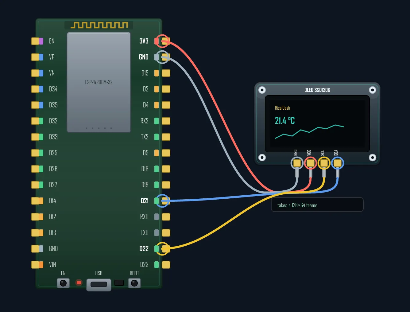
The classic 0.96" OLED talks I²C, so it needs only two signal wires — SDA and SCL — plus power. It is high-contrast (pixels are truly off, no backlight), sips power and costs pocket change. 128×64 pixels holds a few lines of text or a small graph — ideal for clocks, weather readouts and a Wi-Fi/IP status line. The SH1106 is a near-drop-in cousin (a small column offset the library handles).
#include <Adafruit_SSD1306.h>
Adafruit_SSD1306 oled(128, 64, &Wire);   // I2C, address 0x3C (SH1106 is near-identical)

void setup() {
  oled.begin(SSD1306_SWITCHCAPVCC, 0x3C);
  oled.clearDisplay();
  oled.setTextSize(2);
  oled.setTextColor(SSD1306_WHITE);
  oled.setCursor(0, 0);
  oled.println("24.7 C");
  oled.display();                        // push the frame to the panel
}
2. Colour TFT (ST7789 / ILI9341 / ST7735) — full colour over SPI
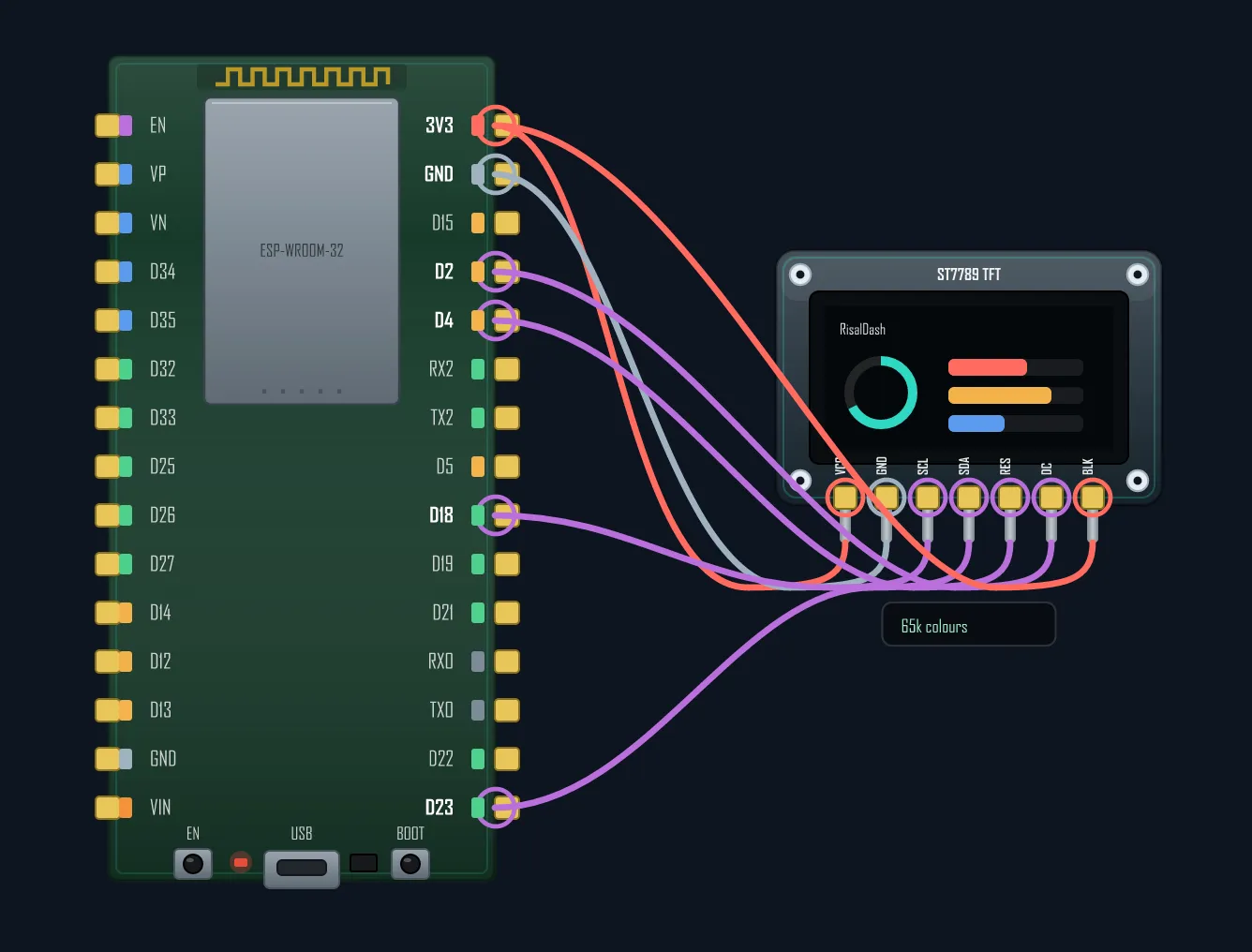
A colour TFT over SPI gives you 65,000 colours and a
refresh fast enough for live charts, menus and images — the workhorse when you want a real dashboard. It
costs more pins than I²C (SCK, MOSI, DC, CS, RES + backlight) and the backlight draws steady current, but
the payoff is a proper UI. The go-to library is TFT_eSPI, where you set the pins once in
User_Setup.h. Cheap modules often label SCK/MOSI as SCL/SDA — same SPI, just
confusing silkscreen.
#include <TFT_eSPI.h>
TFT_eSPI tft = TFT_eSPI();               // SPI pins are set once in User_Setup.h

void setup() {
  tft.init();
  tft.setRotation(1);
  tft.fillScreen(TFT_BLACK);
  tft.setTextColor(TFT_CYAN, TFT_BLACK);
  tft.setTextSize(3);
  tft.drawString("24.7 C", 20, 20);      // a full 65k-colour UI
}
3. Touch TFT (ILI9341 + XPT2046) — a panel you tap
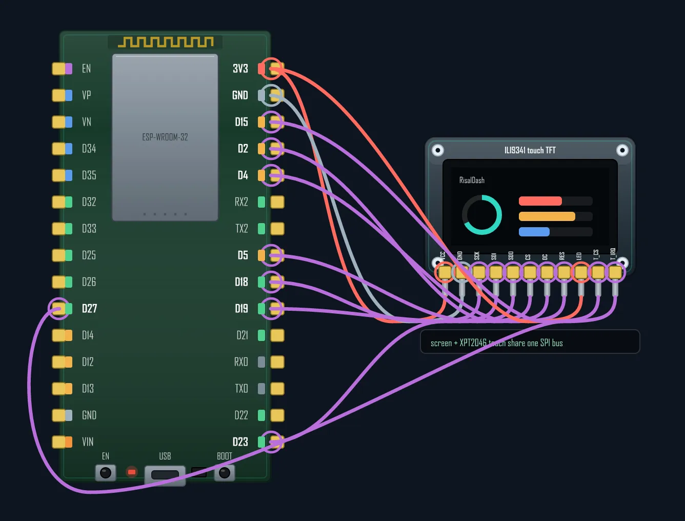
Add a touch layer and the TFT becomes a control surface: home-automation panels, thermostats, handheld remotes. The trick worth knowing — the display and the XPT2046 touch controller share the same SPI bus (SCK/MOSI/MISO); the touch chip only needs its own T_CS chip-select and an optional T_IRQ interrupt. That keeps the pin count sane. The famous Cheap Yellow Display is exactly this: an ESP32 + 2.8" ILI9341 + XPT2046 on one board.
#include <TFT_eSPI.h>
TFT_eSPI tft = TFT_eSPI();               // screen + XPT2046 touch share one SPI bus

void loop() {
  uint16_t x, y;
  if (tft.getTouch(&x, &y)) {            // T_CS + T_IRQ report the press
    tft.fillCircle(x, y, 4, TFT_CYAN);   // draw where the finger landed
  }
}
4. E-Ink (E-Paper) — draws power only when it changes
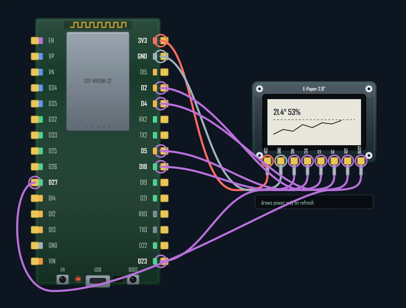
E-Ink is the battery champion: it pulls current only while the image updates, then holds the picture for free — and it is perfectly readable in direct sunlight, like paper. Perfect for shelf tags, room signs, calendars and slow clocks that run for months on a coin cell. The catch is refresh: a full update takes hundreds of milliseconds to a couple of seconds and often flashes, so it is useless for animation. It wires over SPI much like a TFT, plus a BUSY line the panel drives back to the MCU. The common library is GxEPD2.
#include <GxEPD2_BW.h>
// 2.9" panel, pins: CS=5, DC=2, RST=4, BUSY=27
GxEPD2_BW<GxEPD2_290, GxEPD2_290::HEIGHT> epd(GxEPD2_290(5, 2, 4, 27));

void setup() {
  epd.init();
  epd.setFullWindow();
  epd.firstPage();
  do {
    epd.fillScreen(GxEPD_WHITE);
    epd.setCursor(10, 40);
    epd.print("+23 C");                  // then it holds the image on zero power
  } while (epd.nextPage());
}
Before you solder
Two things save the most grief. First, logic level: ESP32 GPIO is 3.3 V — most modules are fine, but a 5 V-only display driven from an Arduino needs care in reverse. Second, pins: a colour or touch screen can claim half your GPIOs, so plan them before you wire — especially on all-in-one screen boards where the display already owns most of the header. Sketch the connections in BoardLab first to see which pins stay free.
Wire your screen visually, then see which GPIOs are left for sensors.