
Guide · I²C · Troubleshooting
Your I²C sensor isn’t showing up? Here’s the fix, in order
You wired a BME280 (or an OLED, or an MPU6050), flashed your sketch, and got… nothing. The board can’t see the sensor. Nine times out of ten it’s one of four things — and they’re quick to check in the right order. Works the same on ESP32, ESP8266 and Arduino.
If you want the physical picture of what I²C actually does on the wire — START, ACK, clock stretching — see the interactive one-byte-six-buses explainer. This post is the practical counterpart: the bus is silent, now what?
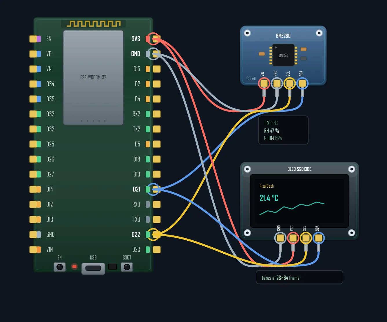
Step 1 — Always scan the bus first
Never debug blind. Every I²C device answers on a 7-bit address, and you can ask the bus who’s home. Flash this and open the Serial Monitor at 115200:
#include <Wire.h>

void setup() {
  Serial.begin(115200);
  Wire.begin();               // ESP8266: D2/D1  ·  ESP32: 21/22  ·  Uno: A4/A5
}

void loop() {
  byte found = 0;
  Serial.println("Scanning I2C bus...");
  for (byte addr = 1; addr < 127; addr++) {
    Wire.beginTransmission(addr);
    if (Wire.endTransmission() == 0) {          // 0 = the device ACKed
      Serial.printf("  found device at 0x%02X\n", addr);
      found++;
    }
  }
  Serial.println(found ? "done." : "No devices found — check wiring & pull-ups.");
  delay(3000);
}
Three outcomes, three diagnoses:
- Your sensor’s address shows up (e.g.
0x76for a BME280) — wiring and power are fine; the bug is in your driver code or the wrong library address. - A different address shows up — you’ve got the wrong part or the wrong address (many boards let you move between two addresses with a solder jumper).
- “No devices found” — the electrical layer is broken. Read on.
Prefer a scanner on a web page instead of a serial cable? The RisalDash I2C-Scanner example lists every address with a best-guess of the chip, live in the browser.
Step 2 — Pull-up resistors (the #1 cause of a silent bus)
I²C outputs are open-drain: a device can only pull a line down to 0. What pulls it back up to logic high is a pair of pull-up resistors — one on SDA, one on SCL, to 3V3. Without them the lines float, nothing reads high, and the scan finds nothing at all.
- Many breakout boards already have pull-ups (often 10 kΩ or 4.7 kΩ). One sensor on a short wire usually just works.
- Add your own only if the bus master board has none. Typical values: 4.7 kΩ at 100 kHz, 2.2 kΩ at 400 kHz — two resistors for the whole bus, not per device.
- Stacked too many modules that each carry pull-ups? The parallel resistance drops too low and the lines can’t be pulled up cleanly — remove the extras.
The value is a trade-off: smaller resistance = crisper edges but more current; the datasheet limit is the bus capacitance (≤400 pF), which brings us to the next trap.
Step 3 — Long wires kill I²C
I²C was designed for chips on one board — centimetres, not metres. Every extra centimetre of wire adds capacitance, the rising edge rounds off, and past ~400 pF the master can’t tell a 1 from a 0. Symptoms: it works on the bench, then flakes out once you route the sensor across the room.
- Drop the speed to 100 kHz (or lower):
Wire.setClock(100000); - Use stronger pull-ups (2.2 kΩ) to fight the capacitance.
- Use twisted or shielded pairs, keep runs short, and don’t share a ribbon cable with noisy signals.
- Genuinely need metres? I²C is the wrong bus — use a differential one (RS-485/CAN). See why I²C is short-range.
Step 4 — Two sensors, one address
The scan shows a device, but your second identical sensor is invisible — because they share the same
fixed address. Two BME280s both answer on 0x76 and clobber each other. Fixes:
- Address pin — most sensors expose an
ADDR/SDOpin that flips them to a second address (e.g.0x76→0x77). Tie one high, one low. - An I²C multiplexer — a
TCA9548Agives you 8 isolated sub-buses, so eight identical sensors coexist behind one address. - A second bus — ESP32 has two hardware I²C peripherals; run
Wire1.begin(sda2, scl2)on different pins.
Still nothing? The usual last suspects
- SDA/SCL swapped — the classic. SDA→SDA, SCL→SCL; crossing them looks identical but the bus stays silent.
- Voltage levels — a 5 V sensor on a 3.3 V ESP32 (or vice-versa) needs a level shifter; don’t wire 5 V straight into an ESP32 pin.
- Power — a hungry module browning out the 3V3 rail drops off the bus. Give it a solid supply and a decoupling cap.
- A stuck slave holding SDA low locks the whole bus. Recover by pulsing SCL up to
9 times before
Wire.begin(), or just power-cycle.
Work the list top to bottom — scan, pull-ups, wire length, addresses, then the stragglers — and a dead I²C bus almost always comes back to life within a few minutes.
Wire your own sensor and export a clean diagram — right in the browser, no Fritzing.