
Guide · Hardware · Levels
3.3V ↔ 5V: how to not fry your ESP32
Half the sensors and modules in the Arduino world run at 5 V. The ESP32, ESP8266 and most modern chips run at 3.3 V. Wire a 5 V output straight into a 3.3 V pin and you can damage it on the spot. Here’s why they don’t mix, when you can skip the shifter, and three clean ways to bridge them.
This is the “how is a level read?” question from the bus fundamentals made painfully practical — and it’s the single most common way beginners kill an ESP32 pin.
Why 3.3V and 5V don’t just work together
Two separate problems, one in each direction:
- 5 V → 3.3 V input (the dangerous one). An ESP32 GPIO is rated to about 3.6 V max. Push 5 V into it and you exceed the input’s protection diodes — sometimes it survives, often it degrades or dies. This is what fries pins.
- 3.3 V → 5 V input (the silent one). A 3.3 V “high” may sit below what a 5 V chip counts as logic-high (often ~3.5 V), so the 5 V device reads nothing or behaves erratically. Nothing burns, but it doesn’t work.
First — do you even need a shifter?
Check before adding parts:
- Many 5 V modules are perfectly happy being read by 3.3 V logic and driven from it — check the datasheet for “3.3 V compatible I/O”.
- On I²C, if you power the pull-ups from 3.3 V and the sensor tolerates it, the bus often just works — open-drain lines only ever get pulled to 3.3 V.
- Only the 5 V → 3.3 V direction is actually dangerous. A 3.3 V signal into a 5 V input is never harmful, only sometimes insufficient.
Method 1 — Resistor divider (one direction)
For a single 5 V output going into a 3.3 V input — a sensor’s TX into the ESP32’s RX — two resistors are all you need:
5V TX ──[ R1 = 1kΩ ]──┬──> 3V3 RX (safe)
                      │
                   [ R2 = 2kΩ ]
                      │
                     GND

Vout = 5V × R2 / (R1 + R2) = 5 × 2 / 3 ≈ 3.3 V
// One direction only (5V -> 3V3). Do NOT use on an I²C SDA line.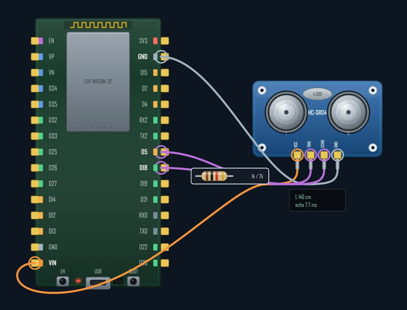
Cheap and reliable, but one-way only and a bit slow (the resistance plus wire capacitance rounds fast edges). Never put it on a bidirectional line like I²C SDA.
Method 2 — BSS138 MOSFET (bidirectional, the go-to)
The classic 4-channel “logic level converter” board is a handful of BSS138 MOSFETs. Each channel shifts both directions automatically, which is exactly what I²C needs (both SDA and SCL are bidirectional). Wire the high side to 5 V, the low side to 3.3 V, share ground, and pass your signals through. It’s a couple of dollars and solves 90% of cases.
Method 3 — Dedicated shifter ICs (many/fast lines)
For an 8-bit parallel bus or fast SPI, use a purpose-built IC: TXS0108E (auto-direction,
open-drain friendly) or TXB0104 (push-pull, faster, not for I²C). They handle higher
speeds and more channels cleanly than a divider or a single MOSFET.
Gotchas
- A divider is one-way. Using it on I²C SDA breaks the bus — the sensor can’t pull the line the other way. Use a BSS138 there.
- Both voltage references. A level-shifter module needs both HV (5 V) and LV (3.3 V) supplies connected, plus a common ground — miss one and it does nothing.
- Push-pull vs open-drain. TXB-class parts don’t work on open-drain buses like I²C; use TXS-class or BSS138 there.
- Common ground is mandatory — the two sides must share GND or the levels mean nothing.
Rule of thumb: one 5 V signal in → a divider. A bidirectional bus (I²C) → a BSS138 board. Many or fast lines → a proper shifter IC. Get it right once and your ESP32 pins live a long life.
Fighting a silent I²C bus? Level mismatch is one of the usual suspects.