
Guide · LEDs · Electronics
Everything about the humble LED
The LED is the first thing everyone blinks — and the first thing everyone burns out. Behind that tiny glow is real physics: the colour comes from the semiconductor, each colour needs a different voltage, and a single resistor keeps it alive. Here’s all of it, with the go-to resistor values for ESP32 and Arduino.
Why LEDs come in different colours
The colour of an LED has nothing to do with the plastic of its case — a clear LED can glow red, a coloured one can glow white. The colour is set by the semiconductor material of the tiny crystal inside: different materials release photons of different energy, and photon energy is colour. That’s why you can’t just “paint” an LED a new colour.
| Colour | Semiconductor | Forward voltage (Vf) |
|---|---|---|
| Infrared | GaAs | ~1.2–1.6 V |
| Red | AlGaInP | 1.8–2.2 V |
| Orange | AlGaInP | 2.0–2.2 V |
| Yellow | AlGaInP | 2.0–2.2 V |
| Green | GaP / InGaN | 2.0–3.2 V |
| Blue | InGaN | 3.0–3.4 V |
| White | InGaN + phosphor | 3.0–3.4 V |
| UV | AlGaN | 3.2–3.8 V |
Note white: there’s no “white” semiconductor — a white LED is a blue die with a yellow phosphor coating that mixes up to white.
What’s inside a 5 mm LED
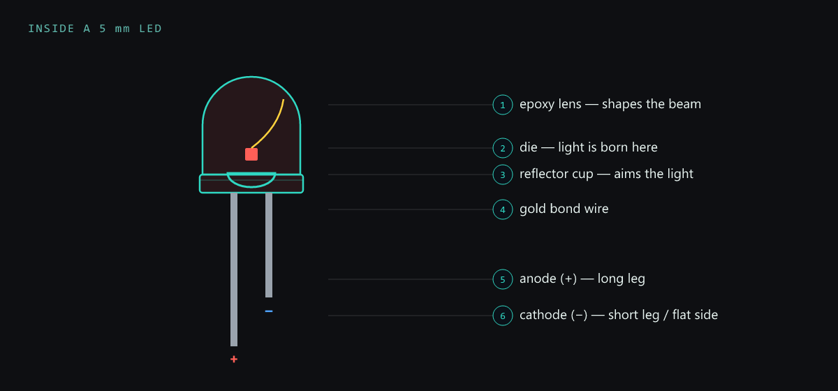
An LED isn’t just coloured plastic — it’s a little optical machine. The light is born in a semiconductor die less than a millimetre across, held in a reflector cup that aims the light forward, connected by a hair-thin gold bond wire, and focused by the epoxy lens. The two legs are not interchangeable: the long leg is the anode (+), the short leg — next to the flat side of the rim — is the cathode (−).
Why each colour has its own voltage
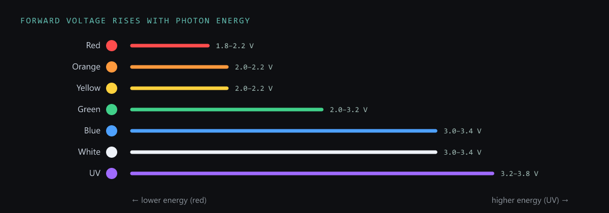
When current flows, electrons drop to a lower energy level and emit a photon. A bluer, higher-energy photon needs a bigger energy drop — which means a higher forward voltage (Vf). So red sits around 2 V while blue, white and UV need 3–3.8 V. This matters directly on a 3.3 V ESP32: a blue or white LED is already close to the rail, so it needs only a small resistor (and a red one needs a bit more).
Sizing the series resistor
Never wire an LED straight to a pin. An LED barely limits its own current, so without a resistor it pulls too much and burns out (and can stress the pin). The resistor sets the current with Ohm’s law — subtract the LED’s forward voltage from the supply, divide by the current you want:
// Series resistor for an LED:  R = (Vsupply − Vf) / I
//
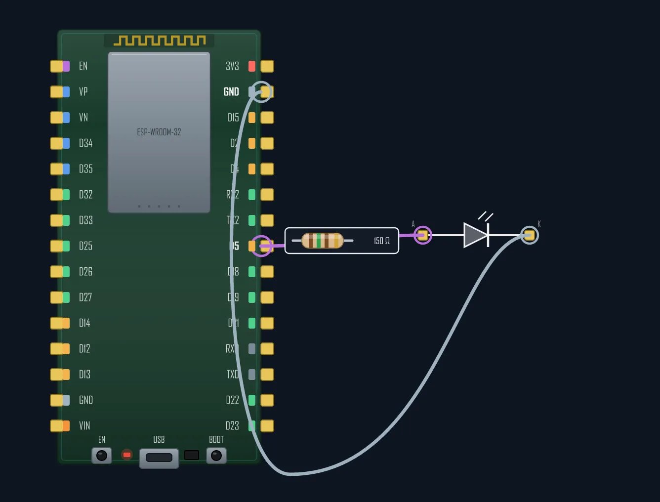
// Red LED (Vf ≈ 2.0 V) at 10 mA on a 3.3 V ESP32 pin:
//   R = (3.3 − 2.0) / 0.010 = 130 Ω  →  use 150 Ω (nearest common)
// Same red LED on a 5 V Arduino pin:
//   R = (5.0 − 2.0) / 0.010 = 300 Ω  →  use 330 Ω

void setup() {
  ledcAttach(2, 5000, 8);      // GPIO2, 5 kHz, 8-bit — hardware PWM dimming
}

void loop() {
  for (int d = 0; d <= 255; d++) { ledcWrite(2, d); delay(4); }   // fade up
  for (int d = 255; d >= 0; d--) { ledcWrite(2, d); delay(4); }   // fade down
}
Aim for 5–15 mA for a normal indicator (an ESP32 pin should stay under ~20 mA anyway; see 3.3 V vs 5 V). Rather than recompute every time, these are the everyday values (blue/white LED at 10 mA):
| Supply | Resistor | Power rating |
|---|---|---|
| 3.3 V (ESP32) | 33 Ω | ¼ W |
| 5 V (Arduino) | 220 Ω | ¼ W |
| 9 V | 620 Ω | ¼ W |
| 12 V | 910 Ω | ¼ W |
| 24 V | 2.2 kΩ | ½ W |
| 230 V AC | 24 kΩ | 5 W (needs a bridge rectifier) |
The quick rule of thumb: on a 3.3 V ESP32 pin use 33–100 Ω; on a 5 V Arduino pin use 220–330 Ω. Want smooth dimming instead of on/off? Drive the pin with hardware PWM — the resistor stays exactly the same.
Wiring an LED to a board? Draw it in the browser and export a clean diagram.